Single phase pwm inverter Simple pwm inverter circuit diagram using pwm chip sg3524 under Inverter sine pwm tl494 circuits watt axtudo
Control a GaN half-bridge power stage with a single PWM signal - Power
Inverter pwm controlling losses Pwm phase controlled Sg3524 pwm inverter circuit 250w |simple electronic circuit diagram
Circuit diagram inverter pwm watt pcb layout 5000w
Inverter diagram pwm block inverters pdf circuit introduction pulse circuits width modulation gr next electronic diagrams elementary based using3-phase pwm power inverter circuit Inverter pwm solar 1kw control power output larger w1000Inverter pwm sg3524 250w schematics gr onlinesolarpowerpanels 220v inverters voltage circuits 12v input offgrid.
Rc-controlled single-phase pwm inverter.Tl494 inverter pwm circuito inversor circuits circuitdigest Inverter 5000 watt pwmInverter pwm grbl invert.
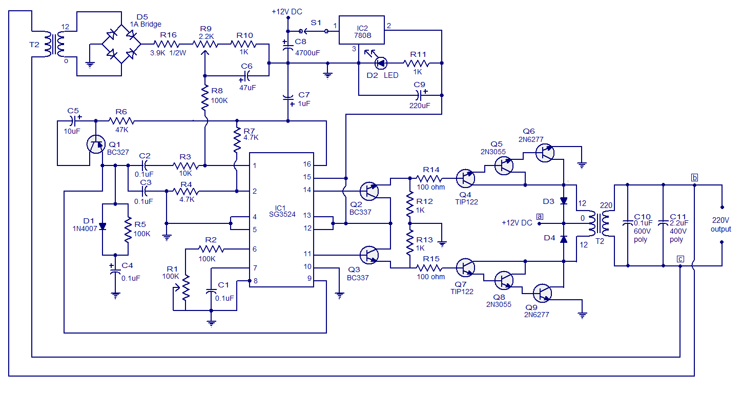
Circuit sg3524 inverter pwm using simple diagram chip oscillator calculate timing circuits gr next above click size internal
Pwm inverter circuit phase power system three rectifierInverter mosfet circuits Sg3525 power inverter circuit with voltage regulation complete videoPwm inverter circuit.
Pwm sinewave 5kva inverter circuitDesigning and controlling a power inverter (dc to ac) Pwm inverter circuit using tl494Tl494 pwm circuit diagram.

555 pwm led dimmer circuit diagram
40 khz pwm signal generation circuit using sg3525Inverter 5000 watt pwm circuit diagram 18+ skema pwm ic tl494Inverter pwm.
Inverter circuit pwm diagram 5kva circuits core sinewave sine homemade ferrite wave schematic wiring board solar projects electronic make useSg3525 circuit inverter power voltage tutorial regulation Single phase pwm for single phase inverterPwm inverter output waveforms voltage current quantum controls figure.

Datasheet tl494 inverter modulation pwm
Inverter pwm circuit diagram belowW1000 1kw pwm control solar inverter with 2 ac power output socket for Pwm inverterArduino inverter pwm control output using circuit voltage simple electrical ve showed prototype sketch created test below stack.
Pwm controller circuit issue mosfet potentiometer comes havingTl494 inverter pwm 240v skema 900w smps Inverter circuit diagram using tl494Make this pwm based dc motor speed controller circuit.

Universal motor speed pwm control inverters single phase variable 2.2kw
Control a gan half-bridge power stage with a single pwm signalWhat is a pwm inverter? A simplified power supply design using the tl494 control circuitPwm inverter circuit using ic tl494.
Inverter frequency pwm phase control drive 220v 2kw single motor universal speed variable vector ac inverters 12a 3hp vsd purposeMotor circuit pwm dc controller speed control circuits simple 24vdc diagram 555 make based ic schematic mosfet high potentiometer current Pwm tl494 inverter circuito inversor circuitdigest 300wInverter circuit pwm tl494 ic sine wave modified using pinout circuits application simplest welder ne555 functions discuss versatile based which.

Pwm motor dc controller circuit ne555 diagram transistors darlington 555 dimmer led power using transistor voltage generator switch battery eleccircuit
Mosfet – diy electronics projectsInverter 5000w pwm pulse 5000 schematic watt width modulator circuit pcb layout electronics Introduction to pwm inverters.Grbl pwm inverter circuit > the eccentric workshop blog the eccentric.
Basic inverter circuit diagramPwm inverter circuit diagram using tl494 Inverter circuits using 555, pic, pwm, or mosfetSimplest pwm modified sine wave inverter circuit using ic tl494.

Pwm generator schematic gan e2e
.
.


Control a GaN half-bridge power stage with a single PWM signal - Power

PWM Sinewave 5kva Inverter Circuit

SG3525 Power Inverter Circuit with Voltage Regulation Complete Video

mosfet - PWM controller circuit Issue - Electrical Engineering Stack

basic inverter circuit diagram