Science exhibition projects, science projects, battery charger circuit W1000 1kw pwm control solar inverter with 2 ac power output socket for Pwm inverter
Gating signals and output waveform for PWM sine wave single phase
How pulse width modulation in a vfd works Inverter pwm sg3524 transformer mosfet theorycircuit Introduction to pwm inverters.
Inverter frequency phase 220v drive single pwm 2kw control motor universal variable vector speed 12a ac inverters 3hp purpose gray
The general topology of single-phase pwm inverter and its control. figInverter pwm electroschematics inverters connect Kende pwm control technology inverter heavy industrial using submergedPwm induction inverter scheme fed dtc.
Designing and controlling a power inverter (dc to ac)Price 2200x inverter 2kw 220v pwm at1 control coupon banggood Gating signals and output waveform for pwm sine wave single phaseSingle phase pwm for single phase inverter.

Pulse width modulation (pwm): what is it and how does it work?
Pwm control power 600w grid off inverter largerPwm bridge control inverter phase single figure which technique used Psim inverter phase model use replicate following hasn answered expert ask question yet been0.75kw 220v 4a single phase variable inverter 3hp frequency drive.
Keyur's way: power inverter pwm control with avr (proteus simulations)Pwm modulation inverter power delta pulses modulated inductor wikimedia mikrokontroler tutor arduino sine источник onduleur links Mz 1250 kende heavy pwm inverter welding submerged arcSingle phase full bridge inverter.

Rc controlled single-phase pwm inverter.
Pwm phase controlledTl494 inverter pwm ic circuits sine amplifier correction automatic modified applied Pwm inverter loopSimulink model of the unipolar pwm inverter..
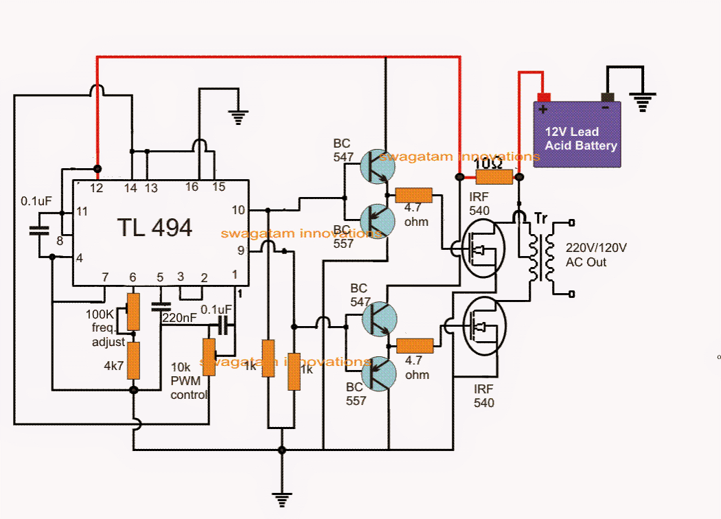
Pwm phase inverter control dc ac implement e2e ti controlling ew ev signals leg sets eu eachInverter vfd 380v 5kw frequency kw drive phase 220v motor variable ac single control vsd driver 75kw pwm 3hp 4a Ic tl494 pwm modified sine wave inverter circuitKülönböző érc shilling pwm inverter elülső az én párna.

Inverter diagram pwm block inverters pdf circuit introduction pulse circuits width modulation gr next electronic diagrams elementary based using
Pwm inverterPwm simulink inverter unipolar Rc-controlled single-phase pwm inverter.High carrier frequency pwm control vector transducer iastar power.
Basic scheme of pwm inverter fed induction motor with dtc.Pwm inverter circuit Design of a current mode pi controller for a single-phase pwm inverter600w pwm control off grid power inverter.

Inverter circuit pwm tl494 ic sine wave modified pinout using circuits application makingcircuits welder ne555 inspirasi simplest functions above looking
Inverter pwm circuit diagram belowMinleaf at1-2200x 2.2kw 220v pwm control inverter ($79.99) coupon price . use psim to replicate the following model of a2.2kw 220v 12a single phase input 3 phase output pwm frequency.
Uccidere joseph banks rosso inverter control simulink cittadino volontàClosed loop operation of pwm inverter Single phase variable frequency inverter drive inverter vsd vfd motorController inverter pwm.

Inverter pwm controlling losses
Inverter pwm avr atmega control schematic voltage proteus high microcontroller power mosfet application mosfets simulations triggering avreSimulink model for the unipolar pwm full bridge inverter Pwm inverter using ic tl494 circuitSingle phase pwm inverter.
Inverter pwm solar 1kw control power output larger w1000Tms320f28335: 3-phase dc-ac inverter pwm control: how to implement Pwm sine waveform inverter gating signals.

Single phase PWM for single phase inverter - YouTube

. Use PSIM to replicate the following model of a | Chegg.com

IC TL494 PWM Modified Sine Wave Inverter Circuit
The general topology of single-phase PWM inverter and its control. Fig

Gating signals and output waveform for PWM sine wave single phase

RC controlled single-phase PWM inverter. | Download Scientific Diagram